For each bus k, determine which of the variables V, 8k, P, and Qx are input data and which are unknowns. Note that the loads at buses 2 and 3 are inductive since Q2 = -Qu2 = -2.8 and -Q23 = -0.4 are negative. Bus 3, to which a generator and a load are connected, is a voltage-controlled bus. As shown in Table 6.1, bus 1, to which a generator is connected, is the swing bus. Input data are given in Tables 6.1, 6.2, and 6.3.

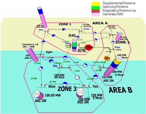
Verify your result using Power World Simulator case Example 6_9.ĮXAMPLE 6.9 Power flow input data and Ybus Figure 6.2 shows a single-line diagram of a five-bus power system.

Determine the new values for the second row of Ybus.

Transcribed image text: 6.29 In Example 6.9, double the impedance on the line from bus 2 to bus 5.


 0 kommentar(er)
